Floating offshore substation model test shows potential
The energy transition is a hot topic within the offshore industry nowadays, and for good reason. Effects of climate change are imminent and it is necessary to invest in the development of large scale offshore renewables. What the exact energy mix will look like in the future is difficult to predict, but it is clear that offshore renewable energy will grow immensely in upcoming years.

Floating wind energy capacity
According expectations, 1800 Gigawatts (GW) of offshore wind energy will be generated by 2050, of which 250 GW from floating wind farms. Suitable regions to generate floating offshore wind can be found in California and South-East Asia, but also in Europe, where the main focus is on the Mediterranean, North Sea, Bay of Biscay, Baltic Sea and the Aegean Sea. All of these areas have deep water and have suitable wind conditions for generating sustainable energy.
To efficiently transport 250GW of renewable energy from sea to shore, offshore substations are required. These substations collect the wind energy (AC) from the farm, convert the electricity to high-voltage direct current (HVDC) or high-voltage alternative current (HVAC) and transports this through 2 or 4 export cables to shore. By doing so, the power losses during transport from substation to shore are significantly reduced. These substations are already widely used in shallow waters, where the station is supported by a jacket or other bottom-founded solutions. Each substation is typically connected to 100 to 150 wind turbines, generating between 1.0 and 2.0 GW of power.
At water depths beyond 150 meter, the costs of the renowned ‘bottom-founded’ solutions increase exponentially, making floating solutions an interesting alternative. It is expected that in water depths up to 300 meters, the substation might still be bottom-founded, while the turbines already utilize a floating solution. In fields with water depths beyond 300 meters, a floating offshore substation (FOSS) will be required.
With an expected required floating wind energy capacity of 250GW in 2050, the market is presented with a significant challenge. Assuming that the first full-scale floating substation will be commissioned in 2035. Eight (8) to ten (10) substations of 2 GW are to be built each year over the period of 2035 to 2050, to reach this forecast.
Current market challenges
At the moment, there is a significant amount of floating concepts in development to support the floating wind turbine. Recently, companies have started to investigate the technologies for floating offshore substations as well, but it is fair to say that there are no proven designs in the market.
The main challenge at the moment is that the dynamic conditions, as encountered by a FOSS, are uncharted territories for equipment and cable manufacturers (OEMs). The high-voltage equipment, as existing today, has not been designed for continuous motions and accelerations as will be experienced on a floating platform.
For a financial perspective, floating wind solutions are expected to be more expensive than bottom-founded solutions. This is of course dependent on a large range of factors, like design life, water depth, size of the wind farm and many other aspects. On the other hand, being able to develop deep water sites would decrease the constraints on hub heights, shipping routes as well as the social impact on offshore wind. And even though these aspects will reduce project expenses, it is difficult to express this in reduced cost for the overall development. And in the end, differences in material cost between bottom-founded and floating substations are more prominent and easier to express. One could argue that the cheapest option for a floating substation is to refurbish an existing tanker hull and transform it into floating substation, as is being done for floating production, storage and offloading (FPSO) units. However, this solution is not considered feasible, due to the expected allowable accelerations of the HV equipment, which are still being investigated by the OEMs.
From a technical point of view, conceptual studies are challenging and complex, since there are still a lot of unknowns regarding:
- the standards to be used in overall design of the floater (1),
- the allowable motion criteria of the HV equipment (2)
- the fatigue capacity of the inter-array and export cables (3).
In recent years Nevesbu and Iv have focussed on investigating these three topics in more detail and the current status is discussed in the remainder of this article. It is important to realize that wind turbines are capable of operating in conditions up to Beaufort 8, which means that the floating substation must be operational in waves of 8 to 12 meters high. This makes bullet point 2 and 3 even more challenging.
Floating Offshore Substations standards
In 2021, the Floating Offshore Substations (FOSS) JIP, initiated by DNV, was initiated. The main goal was to study gaps in the current standards required for floating offshore substation, proposals to bridge those gaps, as well as exploring the current state of technology and design. Next to development of this standard, a recommended practice is prepared for the design and analysis of high voltage export cables. Nevesbu as well as Iv were closely involved in this JIP, together with numerous companies from the industry. This JIP has brought more insight in the remaining challenges and technology gaps for floating offshore wind substations and in the preferred standards to be used for floating solutions. At the moment, the DNV-ST-0145 is being updated by DNV and will be presented for review to the JIP in 2024.
At this moment, the FOSS JIP Phase 1 is closed and the second phase is being prepared and will commence in the upcoming year, with the aim to close the identified technology gaps and to also consider different technologies for floating offshore substations.
Concept development
Nevesbu and Iv have investigated and compared several floating substation concepts in recent years. Different floater types were investigated, like SPARs, buoys, semi-submersibles and tension leg platforms.
Each concept must adhere to the established requirements for offshore wind energy, avoiding excessive steel weight and maintaining simplicity in terms of fabrication. Furthermore, it is essential to ensure safety and reliability, while also guaranteeing very high availability and a platform lifespan of no less than 30 to 40 years. In addition, the social costs of supplying sustainable electricity must remain affordable, and the solution itself should therefore not be too expensive in terms of costs.
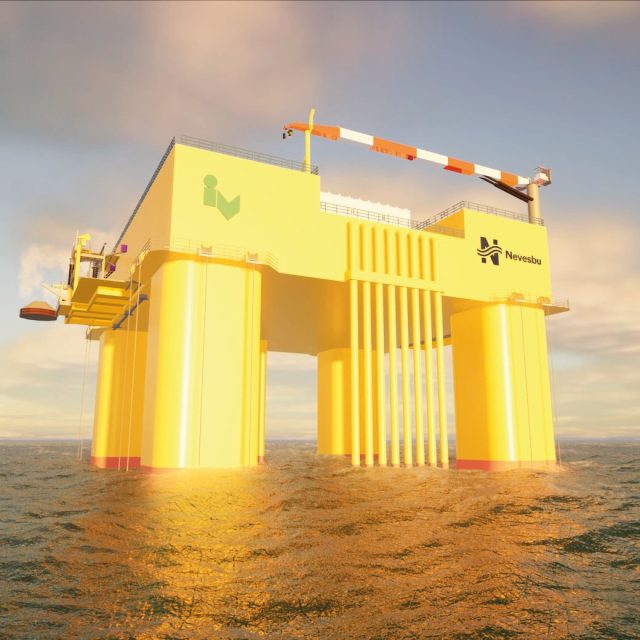
Based on these principles and requirements, a selection was made for the most promising floater type. At this moment, the main focus within Nevesbu is on the development of a substation concept, which is based on proven Tension Leg Platform (TLP) technology.
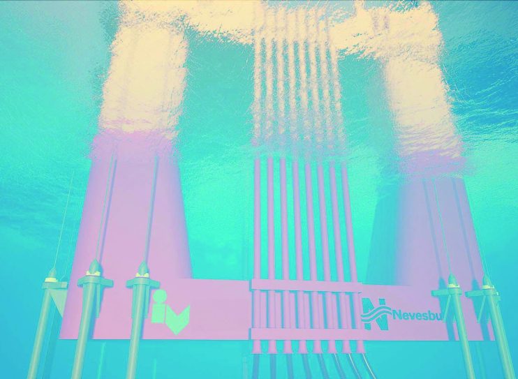
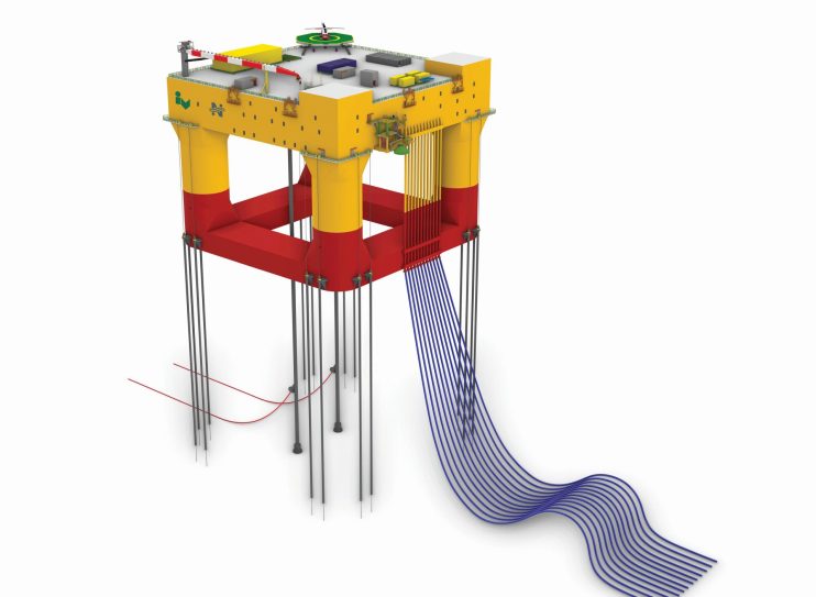
The concept is developed for transforming 1.4 to 2.0 Gigawatt of power, with a DC export link of 300 to 525kV. A typical HVDC topside weighs about 13,000 to 20,000 ton. The floating HVDC platform has a deck area of 85 by 85 metres and raises approximately 25 metres above the water’s surface. The overall arrangement has been optimized for application on a floating substructure. When the platform is installed at sea, it will be held in position with the help of so-called ‘tendons’ that are vertically anchored to the seabed, which restricts the vertical motions and accelerations.


Cable guide system
Dynamic inter-array cables are being developed and tested at full scale already in the floating wind turbine pilots around the world and are therefore considered to have matured before deployment of the first FOSS units. The DC export cables, on the other hand, are even more fatigue sensitive, due to the large core and surrounding metallic sheath. A cable guide system that solves the fatigue problem for the DC export cable(CGS) has been developed by Nevesbu.
Performing a model test at MARIN
In October 2023, Nevesbu has tested the floating concept with different configurations of the cable guide system (CGS) in model scale. The model test has been performed within the MKB slot provided by MARIN.
Two primary objectives have been established for the model testing campaign. The first series of model tests is conducted to calibrate the numerical model. The second series of tests is centered around the CGS, where the system’s response is examined under different CGS pretension levels in a range of different sea states. To achieve these objectives, the model was equipped with a motion and acceleration sensors and load sensors on each tendon and cable guide.
This information is logged for the expected sea states the substation will be operating in. The maximum wave height tested in the model basin corresponds to the once in 100 year event occurring West of Shetlands, which is Hs > 17.0 meter. A first high-level check has shown that the measured maximum offset, accelerations and CGS loads in irregular waves are comparable to the outcomes from the numerical model. The exact results of these tests are now carefully compared and verified by Nevesbu, using the in-house developed numerical model and the data from MARIN.
To stimulate Dutch maritime innovation, MARIN invites small and medium enterprises (MKB) to test their new ideas and concepts for free to stimulate innovation in the Dutch maritime sector and to lower the threshold for small and medium enterprises to test their new ideas and concepts. The free basin slots allow feasibility checks and improvements in an early phase of a new concept development.
In 2023, MARIN awarded Nevesbu a free basin slot to test the floating substation concept. For MARIN also quite unique to test a deep water floating substation that is based on TLP technology in less than half of the usual basin time and at a fraction of the cost than usual for such a project. Due to the size of the floater, MARIN was able to test at a smaller scale of 1:100 which also allowed for full geometrical scaling of the tendons (350 m water depth). This is important for the proper motion behaviour and set down of the floating substation in waves.
MARIN has tested the substation in its concept basin, with a length of 220 m, a width of 4 m and a depth of 3.6 m. The basin is filled with fresh water and fitted a wave generator at the end of the basin. Opposite the wave generator MARIN installed a passive sinkable wave absorber. The wave generator is equipped with compensation of wave reflections (ARC) from the model and the wave absorbing beach. MARIN has based the wave generation on higher order wave synthesis techniques.
MARIN built the small scale substation model from thin walled PVC parts welded together, resulting in a model of only 25 kg including all instrumentation. The tendons and DC-export cables were made of steel wires with proper stiffness and mass distribution to model the proper dynamic behaviour of the full configuration of floater, tendons and DC export cables. MARIN measured the motions and accelerations and forces on all tendons and DC-export cables. Furthermore, video recordings of each test were made to assess wave run-up on the columns and possible deck-impacts in extreme events.
Finally, MARIN tested a selection of ten different wave conditions with different configurations of the DC export cables. Nevesbu can use the measurement results, time traces sampled at 200 Hz of all measurement signals and video to validate and tune the numerical model of the floating substation.
Floating offshore substation concept status and outlook
After the successful testing campaign of the floating substation, in combination with the in-house developed cable guide system, the FOSS concept is at Technology Readiness Level 3 and ready for further development. Based on this solid concept, more in-depth fatigue life estimations of floater, tendons, cable guide system and HV equipment will be performed to further mature our design solution. Close collaborations with OEMs should be established in parallel to better understand equipment limitations.
Would you like to know more about Nevesbu's floating offshore substation concept? Albert will be pleased to tell you more.
